Maintaining & Repairing Refrigeration Equipment
| As a refrigeration technician, you must be able to maintain, service,
and repair refrigeration equipment. This phase of our course provides
information on different jobs that you may be assigned. It is
not intended to be all encompassing. Manufacturers also provide
instruction manuals to aid you in maintaining and servicing their
equipment |
Servicing Equipment
 Repair and service work on a refrigeration system consists mainly
of containing refrigerant and measuring pressures accurately.
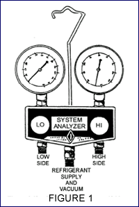
One piece of equipment is the refrigerant gauge manifold set (fig.
1). It consists of a 0-500 psig gauge for measuring pressure at
the compressor high side, a compound gauge (0-250 psig and 0 to
-30 inches of mercury) to measure the low or suction side, and
valves to control admission of the refrigerant to the refrigeration
system. It also has the connections and lines required to connect
the test set to the system. Depending on test and service requirements,
the gauge set can be connected to the low side, the high side,
a source of vacuum, or a refrigerant cylinder. A swiveling hanger
allows the test set to be hung easily, and the three additional
blank connections allow for securing the open ends of the three
lines when the gauge set is not in use. There is always a path
from the low-side and high-side input to the low-side and high-side
gauge.
Another important piece of equipment is the portable vacuum
pump--s a sealed unit consisting of a single-piston vacuum pump
driven by an electric motor. A vacuum pump is the same as a
compressor, except the valves are arranged
so the suction valve is opened only when the suction developed
by the downward stroke of the piston is greater than the vacuum
already in the line. 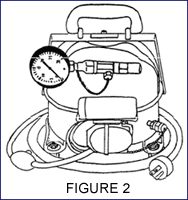 This vacuum pump can develop a vacuum close
to -30 inches of mercury, which can be read on the gauge mounted
on the unit (fig. 2). The pump is used to reduce the pressure
in a refrigeration system to below atmospheric pressure. This vacuum pump can develop a vacuum close
to -30 inches of mercury, which can be read on the gauge mounted
on the unit (fig. 2). The pump is used to reduce the pressure
in a refrigeration system to below atmospheric pressure.
Various manufacturers manufacture hermetic refrigeration systems
used by the Navy; therefore, the connectors and size of tubing
vary. The Table of Allowance provides for a refrigeration service
kit that contains several adapters, wrenches, and other materials
to help connect different makes of systems to the refrigerant
manifold gauge set and the vacuum pump lines. A table affixed
to the lid of the storage container identifies the adapter you
should use for a particular refrigeration unit.
Back to Top |
Transferring Refrigerants
Refrigerants are shipped in compressed gas cylinders as a liquid
under pressure. Liquids are usually removed from the shipping
containers and transferred to a service cylinder
Before attempting transfer of refrigerants from a container
to a cylinder, precool the receiving cylinder until its pressure
is lower than that of the storage container or cylinder. Precool
by placing the cylinder in ice water or a refrigerated tank.
You must also weigh the service cylinder, including cap, and
compare it with the tare weight stamped or tagged on the cylinder.
The amount of refrigerant that may be placed in a cylinder is
85 percent of the tare weight (the weight of a full cylinder
and its cap minus the weight of the empty cylinder and its cap)
To transfer refrigerants, connect a flexible charging line
on a 1/4-inch copper tube several feet long with a circular
loop about 8 to 10 inches in diameter. Be sure to install a
1/4-inch refrigerant shutoff valve in the charging line to the
service cylinder. This valve should be inserted so no more than
3 inches of tubing is between the last fitting and the valve
itself. This arrangement prevents the loss of refrigerant when
the service drum is finally disconnected. The entire line must
be cleared of air by leaving the flare nut on the service cylinder
loose and cracking the storage cylinder valve. This arrangement
allows refrigerant to flow through the tubing, clearing it.
After clearing, tighten the flare nut and then open the valve
on the service cylinder, the valve on the storage cylinder,
and then the 1/4-inch valve in the refrigerant line. When the
weight of the service cylinder shows a sufficient amount of
refrigerant is in the serviced cylinder, close all valves tightly,
and disconnect the charging line at the service cylinder CAUTION - To warm refrigerant containers or cylinders
for more rapid discharge, use care to prevent a temperature
above 120°F because the fusible plugs in the cylinder and
valve have a melting point of about 157°F
Back to Top |
Evacuating and Charging a System
Evacuation
Before a system can be charged, all moisture and air must be
eliminated from the components by drawing a vacuum on the system.
To draw a vacuum on the system, proceed as follows:
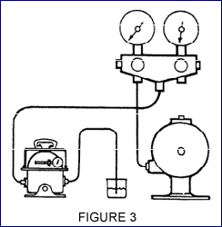 Connect
the portable vacuum pump to the vacuum fitting on the refrigerant
manifold gauge set Connect
the portable vacuum pump to the vacuum fitting on the refrigerant
manifold gauge set- Connect the LO line (suction) to the suction service valve
of the compressor, using appropriate connectors if required
- Turn the suction service valve to mid-position, so vacuum
draws from the compressor crankcase and suction line back
through the evaporator, expansion valve, and liquid line. When the receiver service valve, condenser service valve,
and discharge service valve are open, the pump draws back
through the receiver and condenser to the compressor
- Attach one end of a 1/4-inch copper tube to the vacuum pump
discharge outlet (Fig. 3). Allow the vacuum pump to draw a
vacuum of at least 25 inches. Submerge the other end of the
copper tubing under 2 or 3 inches of clean compressor oil
contained in a bottle
- Continue to operate the vacuum pump until there are no more
bubbles of air and vapor in the oil, which indicates that
a deep vacuum has been obtained
- Maintain the deep vacuum operation for at least 5 minutes,
and then stop the vacuum pump. Leaking discharge valves of
a vacuum pump cause oil to be sucked up into the copper discharge
tube. Keep the vacuum pump off at least 15 minutes to allow
air to enter the system through any leaks. Then start the
vacuum pump. A leaky system causes bubbling of the oil in
the bottle
- Examine and tighten any suspected joints in the line, including
the line to the vacuum pump. Repeat the test
Charging In most small refrigerating systems, low-side
charging (fig. 4) is generally recommended for adding refrigerant
after repairs have been made. After the system has been cleaned
and tested for leaks, the steps to charge the system are as
follows:
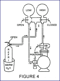 Connect
a line from a refrigerant cylinder to the bottom center connection
on the refrigerant gauge manifold set. Be certain the refrigerant
cylinder is in a vertical position, so only refrigerant in
the form of gas, not liquid, can enter the system. Leave the
connection loose and crack the valve on the cylinder. This
fills the line with gas and clears the air from the line.
After clearing, tighten the connection Connect
a line from a refrigerant cylinder to the bottom center connection
on the refrigerant gauge manifold set. Be certain the refrigerant
cylinder is in a vertical position, so only refrigerant in
the form of gas, not liquid, can enter the system. Leave the
connection loose and crack the valve on the cylinder. This
fills the line with gas and clears the air from the line.
After clearing, tighten the connection- Connect a line from the LOW (LO) valve (suction) on the
gauge manifold set to the suction service valve of the compressor
- Start the compressor
- Open the valve on the cylinder and the LOW (LO) valve (suction)
on the gauge manifold set
- Open the suction service valve on the compressor to permit
the gas to enter the compressor where it will be compressed
and fed to the high side. Add the refrigerant slowly and check
the liquid level indicator regularly until the system is fully
charged. It is easy to check the receiver refrigerant level
in some makes of condensing units because the receiver has
minimum and maximum liquid level indicator valves which show
the height of the liquid level when opened. If a liquid line
sight glass is used, the proper charge may be determined when
there is no bubbling of refrigerant as it passes by the glass.
The sight glass will appear empty
Again, be certain the refrigerant cylinder is in the vertical
position at all times; otherwise, the liquid refrigerant will
enter the compressor and, liquid not being compressible, damage
the piston or other parts of the compressor.
Back to Top |
Refrigerant Leaks
The best time to test joints and connections in a system is when
there is enough pressure to increase the rate at which the refrigerant
seeps from the leaking joint. There is usually enough pressure
in the high-pressure side of the system; that is, in the condenser,
receiver, and liquid line, including dehydrators, strainers, line
valves, and solenoid valves. This is not necessarily true of the
low-pressure side of the system, especially if it is a low-pressure
installation, such as for frozen foods and ice cream, where pressures
may run only slightly above zero on the gauge. When there is little
pressure, increase the pressure in the low-pressure side of the
system by bypassing the discharging pressure from the condenser
to the low-pressure side through the service gauge manifold Small
leaks cannot be found unless the pressure inside the system is
at least 40 to 50 psi, regardless of the method used to test for
leaks.
Halide Leak Detector The use of a halide leak detector
is the most positive method of detecting leaks in a refrigerant
system using halogen refrigerants (R-12, R-22, R-11, R-502,
etc.). Such a detector consists essentially of a torch burner,
a copper reactor plate, and a rubber exploring hose. Detectors
use acetylene gas, alcohol, or propane as a fuel. A pump supplies
the pressure for a detector that uses alcohol. If a pump-pressure
type of alcohol-burning detector is used, be sure that the air
pumped into the fuel tank is pure.
An atmosphere suspected of containing a halogen vapor is drawn
through the rubber exploring hose into the torch burner of the
detector. Here the air passes over the copper reactor plate,
which is heated to incandescence. If there is a minute trace
of a halogen refrigerant present, the color of the torch flame
changes from blue (neutral) to green as the halogen refrigerant
contacts the reactor plate. The shade of green depends upon
the amount of halogen refrigerant; a pale green color shows
a small concentration and a darker green color, a heavier concentration.
Too much of a halogen refrigerant causes the flame to burn with
a vivid purple color. Extreme concentrations of a halogen refrigerant
may extinguish the flame by crowding out the oxygen available
from the air.
Normally, a halide leak detector is used for R-12 and R-22
systems. In testing for leaks always start at the highest point
of the system and work towards the lowest point because halogen
refrigerants are heavier than air.
When using a leak detector, you will obtain the best results
by following the Precautions listed below:
- Be sure the reactor plate is properly in place.
- Adjust the flame so it does not extend beyond the end of
the burner. (A small flame is more sensitive than a large
flame. If it is hard to light the torch when it is adjusted
to produce a small flame, block the end of the exploring hose
until the fuel ignites; then gradually open the hose.)
- Clean out the rubber exploring hose if the flame continues
to have a white or yellow color. (A white or yellow flame
is an indication that the exploring tube is partially blocked
with dirt.)
- Check to see that air is being drawn into the exploring
tube; this check can be made from time to time by holding
the end of the hose to your ear.
- Hold the end of the exploring hose close to the joint being
tested to prevent dilution of the sample by stray air currents.
- Move the end of the exploring hose slowly and completely
around each joint being tested. (Leak testing cannot be safely
hurried. There is a definite time lag between the moment when
air enters the exploring hose and the moment it reaches the
reactor plate; permit enough time for the sample to reach
the reactor plate.)
If a greenish flame is noted, repeat the test in the same area
until the source of the refrigerant is located.
Always follow a definite procedure in testing for refrigerant
leaks, so none of the joints are missed. Even the smallest leaks
are important. However slight a leak may seem, it eventually
empties the system of its charge and causes faulty operation.
In the long run, the extra time spent in testing each joint
will be justified. A refrigerant system should never be recharged
until all leaks are discovered and repaired.
Electronic Leak Detector
The most sensitive leak detector of all is the electronic type.
The principle of operation is based on the dielectric difference
of gases. In operation, the gun is turned on and adjusted in
a normal atmosphere. The leak-detecting probe is then passed
around the surfaces suspected of leaking. If there is a leak,
no matter how tiny, the halogenated refrigerant is drawn into
the probe. The leak gun then gives out a piercing sound, or
a light flashes, or both, because the new gas changes the resistance
in the circuit.
When using an electronic leak detector, minimize drafts by
shutting off fans or other devices that cause air movement.
Always position the sniffer below the suspected leak. Because
refrigerant is heavier than air, it drifts downward. Always
remove the plastic tip and clean it before each use. Avoid clogging
it with dirt and lint. Move the tip slowly around the suspected
leak. Soap and Water Test
Soap and water may be used to test for leakage of refrigerant
with a pressure higher than atmospheric pressure. Make a soap
and water solution by mixing a lot of soap with water to a thick
consistency. Let it stand until the bubbles have disappeared,
and then apply it to the suspected leaking joint with a soft
brush. Wait for bubbles to appear under the clear, thick soap
solution.
Find extremely small leaks by carefully examining suspected
places with a strong light. If necessary, use a mirror to view
the rear side of joints or other connections suspected of leaking.
Back to Top |
Pumping Down
Quality refrigeration repair includes preventing loss of refrigerant
in the system. Whenever a component is removed from the system,
the normally closed system is opened and, unless precautions are
taken, refrigerant is lost to the atmosphere. The best way to
contain the refrigerant (gas and liquid) is to trap it in the
condenser and receiver by pumping down the system.
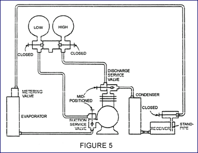 Connections for pumping down a system
To pump down the system, proceed as follows:
- Secure electric power to the unit and connect the refrigerant
manifold test set, as shown in figure 5
- Close the receiver stop (king) valve (by turning the valve
stem inwards as far as it will go), and close both gauges
on the gauge manifold (LO and HI valves)
- Start the compressor and mid-seat the discharge and suction
service valves
- Operate the compressor until the pressure on the suction
(LO) gauge on the manifold shows a vacuum at 0 to 1 psi.
- Stop the compressor. If the pressure rebuilds appreciably,
operate the unit again until pressure registers between 0
to 1 psi. Repeat this step until the pressure no longer rebuilds
appreciably
- When suction pressure remains at about 0 to 1 pound as read
on the compound gauge, then front-seat the suction and discharge
service valves. This procedure traps practically all the refrigerant
in the condenser and receiver
Back to Top |
Recovery, Recycling and Reclaiming Refrigerant
Laws governing the release of chlorofluorocarbon refrigerants
(CFCs) into the atmosphere have resulted in the development of
procedures to recover, recycle, and reuse these refrigerants.
Many companies have developed equipment necessary to prevent the
release of CFCs into the atmosphere. Refrigerant recovery management
equipment can be divided into three categories—recovery,
recycle, and reclaiming equipment.
Recovery
Removing refrigerant from a system in any condition and storing
it in an external container is called "recovery."
Removal of refrigerant from the system is necessary, in some
instances, when repair of a system is needed. To accomplish
this, you can use special recovery equipment, which is now a
requirement when removing refrigerant from a system. This equipment
ensures complete removal of the refrigerant in the system.
Recovery is similar to evacuating a system with the vacuum
pump and is accomplished by either the vapor recovery or liquid
recovery method. In the vapor recovery method (fig. 6), a hose
is connected to the low-side access point (compressor suction
valve) through a filter-drier to the transfer unit, compressor
suction valve. A hose is then connected from the transfer unit,
compressor discharge valve to an external storage cylinder.
When the transfer unit is turned on, it withdraws vapor refrigerant
from the system into the transfer unit compressor, which, in
turn, condenses the refrigerant vapor to a liquid and discharges
it into the external storage cylinder.
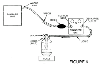
The Vapor Recovery Method |
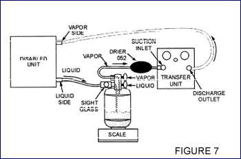
The Liquid Recovery Method |
In the liquid recovery method (fig. 7), a hose is connected
to the low-side access point to the transfer unit compressor
discharge valve. A hose is then connected from the transfer
unit compressor suction valve through a filter-drier to a two-valve
external storage cylinder. A third hose is connected from the
high-side access point (liquid valve at the receiver) to the
two-valve external storage cylinder. When the transfer unit
is turned on, the transfer unit compressor pumps refrigerant
vapor from the external storage cylinder into the refrigeration
system, which pressurizes it. The difference in pressure between
the system and the external storage cylinder forces the liquid
refrigerant from the system into the external cylinder. Once
the liquid refrigerant is removed from the system, the remaining
vapor refrigerant is removed using the vapor recovery method
as previously described.
Most recovery units automatically shut off when the refrigerant
has been completely recovered, but check the manufacturer's
operational manual for specific instructions. You should make
sure that the external storage cylinder is not overfilled. Eighty
percent capacity is normal. If the recovery unit is equipped
with a sight-glass indicator, any changes that may occur should
be noted.
Recycling
The process of cleaning refrigerant for reuse by oil separation
and single or multiple passes through filter-driers which reduce
moisture, acidity, and matter is called "recycling."
In the past, refrigerant was typically vented into the atmosphere.
Modern technology has developed equipment to enable reuse of
old, damaged, or previously used refrigerant. Refrigerant removed
from a system cannot be simply reused—it must be clean.
Recycling in the field as performed by most recycling machines
reduces the contaminants through oil separation and filtration.
Normally recycling is accomplished during the recovery of the
vapor or liquid refrigerant by use of equipment that does both
recovery and recycling of refrigerant.
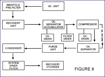
Single-Pass Method of Recycling |
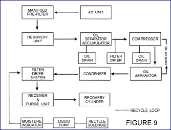
Multi-Pass Method of Recycling |
Recycling machines use either the single-pass or multiple-pass
method of recycling. The single-pass method (fig. 8) processes
refrigerant through as filter-drier and/or uses distillation.
It makes only one pass through the recycling process to a storage
cylinder. The multiple-pass method (fig. 9) recirculates refrigerant
through the filter-drier many times, and after a period of time
or number of cycles, the refrigerant is transferred to a storage
cylinder.
Reclaiming
The reprocessing of a refrigerant to original production specifications
as verified by chemical analysis is called "reclaiming."
Equipment used for this process must meet SAE standards and
remove 100 percent of the moisture and oil particles.
Most reclaiming equipment uses the same process cycle for reclaiming
refrigerant. The refrigerant enters the unit as a vapor or liquid
and is boiled violently at a high temperature at extreme high
pressure (distillation). The refrigerant then enters a large,
unique separator chamber where the velocity is radically reduced,
which allows the high-temperature vapor to rise. During this
phase all the contaminants, such as copper chips, carbon, oil,
and acid, drop to the bottom of the separator to be removed
during the "oil out" operation. The distilled vapor
then leaves the separator and enters an air-cooled condenser
where it is converted to a liquid. Then the liquid refrigerant
passes through a filter-drier into a storage chamber where the
refrigerant is cooled to a temperature of 38°F to 40°F
by an evaporator assembly.
Back to Top |
Component Removal or Replacement
To maintain a refrigerant system at a optimum operating condition
sometimes requires removal or replacement of some component. Procedures
for removal and replacement of some of the components most often
requiring action are covered in this section.
Removing Expansion or Float Valves
To help ensure good results in removing expansion or float
valves, you should pump the system down to a suction pressure
of just over zero. You should do this at least three times before
removing the expansion valve. Plug the opened end of the liquid
line and evaporator coil to prevent air from entering the system.
Repair or replace the expansion valve and connect it to the
liquid valve. Crack the receiver service valve to clear air
from the liquid line and the expansion valve. Connect the expansion
valve to the evaporator coil inlet and tighten the connection.
Pump a vacuum into the low side of the system to remove any
air.
Replacing an Evaporator
To replace an evaporator, pump down the system and disconnect
the liquid and suction lines. Then remove the expansion valve
and the evaporator. Make the necessary repairs or install a
new evaporator as required. Replace the expansion valve and
connect the liquid and suction lines. Remove moisture and air
by evacuating the system. When the evaporator is back in place,
pump a deep vacuum as in starting a new installation for the
first time. Check for leaks and correct them if they occur.
If leaks do occur, be certain to repair them; then pump the
system into a deep vacuum. Repeat the process until no more
leaks are found.
Removing the Compressor
Using the gauge manifold and a vacuum pump, pump down the system.
Most of the refrigerant will be trapped in the condenser and
the receiver. To remove the compressor from service, proceed
as follows:
- Once the pump down is complete, the suction valve should
already be closed and the suction gauge should read a vacuum.
Mid-seat the discharge service valve. Open both manifold valves
to allow high-pressure vapor to build up the compressor crankcase
pressure to 0 psi. Front-seat (close) the discharge service
valve.
- Then crack the suction service valve until the compound
gauge reads 0 to 1 psi to equalize the pressures and then
front-seat the valve.
- Joints should be cleaned with a grease solvent and dried
before opening. Unbolt the suction service and discharge service
valves from the compressor. DO NOT remove the suction or discharge
lines from the compressor service valves.
- Immediately plug all openings through which refrigerant
flows using dry rubber, "cork" stoppers, or tape.
- Disconnect the bolts that hold the compressor to the base
and remove the drive belt or disconnect the drive coupling.
You can now remove the compressor.
Removing Hermetic Compressors
Systems using hermetic compressors are not easily repaired,
as most of the maintenance performed on them consists of removal
and replacement.
- Disconnect the electrical circuit including the overload
switch.
- Install a gauge manifold. Use a piercing valve (Schraider)
if needed.
- Remove the refrigerant using an EPA approved recovery/recycling
unit.
- Disconnect the suction and discharge lines.
- Using a pinching tool, pinch the tubing on both the suction
and discharge lines, and cut both lines between the compressor
and the pinched area.
- Disconnect the bolts holding the compressor to the base
and remove the compressor.
Do not forget to pump down the system and equalize the suction
and head pressure to the atmosphere, if applicable. Wear goggles
to prevent refrigerant from getting in your eyes. After replacement,
the procedures given for removing air and moisture and recharging
the system can be followed; however, the procedures may have to
be modified because of the lack of some valves and connections.
Follow the specific procedures contained in the manufacturer's
manual.
Back to Top |
|

 Repair and service work on a refrigeration system consists mainly
of containing refrigerant and measuring pressures accurately.
One piece of equipment is the refrigerant gauge manifold set (fig.
1). It consists of a 0-500 psig gauge for measuring pressure at
the compressor high side, a compound gauge (0-250 psig and 0 to
-30 inches of mercury) to measure the low or suction side, and
valves to control admission of the refrigerant to the refrigeration
system. It also has the connections and lines required to connect
the test set to the system. Depending on test and service requirements,
the gauge set can be connected to the low side, the high side,
a source of vacuum, or a refrigerant cylinder. A swiveling hanger
allows the test set to be hung easily, and the three additional
blank connections allow for securing the open ends of the three
lines when the gauge set is not in use. There is always a path
from the low-side and high-side input to the low-side and high-side
gauge.
 This vacuum pump can develop a vacuum close
to -30 inches of mercury, which can be read on the gauge mounted
on the unit (fig. 2). The pump is used to reduce the pressure
in a refrigeration system to below atmospheric pressure.
 Connect
the portable vacuum pump to the vacuum fitting on the refrigerant
manifold gauge set
 Connect
a line from a refrigerant cylinder to the bottom center connection
on the refrigerant gauge manifold set. Be certain the refrigerant
cylinder is in a vertical position, so only refrigerant in
the form of gas, not liquid, can enter the system. Leave the
connection loose and crack the valve on the cylinder. This
fills the line with gas and clears the air from the line.
After clearing, tighten the connection


